EQ2 head end electronics:
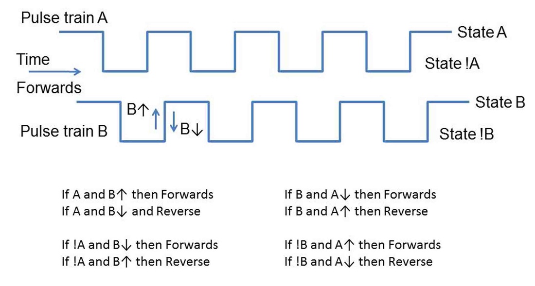
Optical sensors are used to detect the rotation of the gear teeth of the final gear in the gearbox. There are two sensor assemblies, arranged so as to detect the passage of a gear tooth with a small phase difference between them. This phase difference is used to decide the direction of rotation – forwards or backwards. The logic behind this is shown in the diagram.
Optical sensors are used to detect the rotation of the gear teeth of the final gear in the gearbox. There are two sensor assemblies, arranged so as to detect the passage of a gear tooth with a small phase difference between them. This phase difference is used to decide the direction of rotation – forwards or backwards. The logic behind this is shown in the diagram.
The optical device in the sensor is the Kingbright KTIR0821DS. It is an IR emitter and a photo-darlington receiver in a single package. Each sensor assembly uses two devices facing each other across the gear wheel, oriented so that the emitter of one faces the receiver of the other, interrupted by the passage of the gear tooth. The pictures illustrate the
arrangement.
arrangement.
The optical sensors for each axis have their own dedicated head-end microprocessor hanging off them to count ticks and changes of direction. ATMega328 8-bit CPUs are used, which has 32K of program memory and 2K of RAM. This is the same processor as used in the Arduino UNO board, and the Arduino development system is used to develop the code in C and program the CPUs. A 16Mhz crystal and two capacitors are all that is required to use the programed CPUs in a standalone circuit.
The links below have the circuit diagram for the head end electronics as a pdf, and also the C source code as pdf and a txt file. Rename the .txt file to a .ino file and it should be recognised by the Arduino system. The circuit is simple, and consists only of the sensors, CPU and a 7805 voltage regulator, and a few minor components such as LED indicator lamps.
The links below have the circuit diagram for the head end electronics as a pdf, and also the C source code as pdf and a txt file. Rename the .txt file to a .ino file and it should be recognised by the Arduino system. The circuit is simple, and consists only of the sensors, CPU and a 7805 voltage regulator, and a few minor components such as LED indicator lamps.
| encioder_head_end_all.pdf |
| s_circles_head_end_c_code.pdf |
| enk_12r.txt |
One advantage of having emitter and receiver facing each other across such a small distance is that the light intensity is high and the signal picked up at the collector of the photodarlington swings to within a volt of either rail. This means that we can use the Schmitt Triggers at the digital input pins of the ATM328 to act as voltage comparators to give clean triggering from the sensor voltage swing. The pictures show the sensor signal and the microprocessor triggered signal as the final gear of the gearbox spins round.
The sensors from each axis feed a separate CPU. The code in each CPU is identical. The code cycles in a loop reading the sensor inputs (arduino pins 8+9/ CPU pin 14+15), and outputs their state, HI or LO, to arduino pins 11+12/ CPU pins 17+18. On entry to the sensor read routine the pin labelled POLL_MNTR (arduino pin 13/ CPU pin 19) is put LO and on exit from the sensor read routine is put HI. If you have an oscilloscope available you will see this pin output a more or less equal mark/space ratio square wave at around 60KHz. This high sampling rate of the sensors is needed to accurately pick up the phase difference between the two sensor assemblies in order to monitor direction changes. Changes of state of one sensor need to be matched with the state of the second sensor if direction changes are to be detected accurately. Because of the geometry in the gearbox there is limited flexibility to maximise the phase difference, so in practice it may be small. The high sampling rate accommodates this.
Every change of state of one or other of the sensors counts as an encoder ‘tick’, with 17,818 ticks per axis revolution. The program counts ticks in a signed 32bit long int, so there is no possibility of encoder counts rolling over. The positive direction of counting is assumed from the phase relation between what the CPU sees as Channel1 and Channel2, with the count starting at zero. A change of direction will cause the count to decrement. The counting direction convention can be reversed by swapping over the plugs (A/B and C/D in the photographs) from the top and bottom sensors of the relevant axis on the circuit board (more on this in the discussion on the display unit software). The direction state is output at the DIR_OUT pin (arduino pin 10/ CPU pin 16).
When the cpu is not polling the sensor read routine, it is writing out on a serial link the value of the encoder count as an ascii hex string, in the format ‘0xhhhhhhhh,’ where h is an ascii hex digit. The serial link code is a hand rolled RS422 routine running at 9600 baud. The serial output pin is arduino pin 7/ CPU pin 13.
Construction:
Construction is straightforward. The main parts list for the two axes are as follows – I have not listed the minor resistors and capacitors, or general ironmongery (threaded spacers, DB9 plugs, sockets and shells etc). The best way to buy Rs and Cs is as starter kits, say an E12, 0.5 watt resistor kit, a range of mica and polyester caps, and a range of low
voltage electrolytics.
Rapid Electronics (www.rapidonline.com)
1. 2x ATMega328 CPU with Arduino Uno Bootloader programmed, 73-4477
2. 2x 16Mhz 20ppm HC-49US Low Profile Crystal, 90-1428
3. 8x Sensor – 58-0936 Kingbright KTIR0821DS Photointerrupter
4. 2x Plug strip - 22-1705 TruConnect Turned Pin SIL Header 32-Way
5. 2x Socket strip - 22-1751 32 Way Turned Pin Sil Socket
6. 1x Arduino Uno A000066 Board R3, 73-4440
7. 1x Cable USB2 2m A Male to B Male, 19-8660
8. 1x L7805CV +5V 1A VOLTAGE REGULATOR (ST) , 47-3290
9. 2x 47-3136 1N4004 1A 400V SILICON RECTIFIER DIODE
10. 3x 56-0400 Kingbright L-7104LID 3mm Red LED Low Current
11. 5x 56-0405 Kingbright L-7104LGD 3mm Green LED Low Current
12. 2x 56-0410 Kingbright L-7104LYD 3mm Yellow LED Low Current
13. 10x 55-0160 Kingbright 3mm LED Panel Clip
14. 22-0114 Tube of 17 28pin DIL Socket, Narrow7.62mm with Central Support
Sciencestore (www.sciencestore.co.uk)
1. Tripad Board, SRBP board 100 x 160mm with rectangular pads covering three holes at a time. Hole spacing 2.54 x 2.54 (o.1"), 39 strips x 20 (3 hole pads) Part No.: CDT0139
Maplin (www.maplin.co.uk)
1. Tripad board, Product Code JP52G (if you can’t get it at Sciencestore)
2. Enclosure box LH14
The circuit is constructed on tripad stripboard. Be aware that you will probably be inserting and removing the CPU’s from the 28pin sockets on numerous occasions. A flat bladed screwdriver is fine for this, but it helps to have access to both ends of the chip, so try and keep these areas clear of components so you can get the screwdriver into position. Wear an antistatic strap when handling the CPUs. The little plugs and sockets to link the front panel DB9 connectors, LEDs and switch are made from the plug and socket strip and a hot glue gun. The pictures here show the construction of the head end:
Setup:
Once the circuit has been constructed and working, the sensor positions on the gearboxes have to be optimised. Access to an oscilloscope is probably required for this. Firstly rotate each sensor assembly into the path of the gear. Spin the gear wheels and rotate the sensor to find the point where the voltage swing from the KTIR0821DS is
largest. With the ‘scope on the collector of the photodarlington (CPU pins 14+15), aim for a symmetric 3V swing minimum, with a ~1V gap between the two rails. Start with the bottom sensor first, and then adjust the top sensor.
Next put the ‘scope on the DIR_OUT pin (CPU pin 16) and rotate the gear backwards and forwards at various speeds.
Note how the state of the DIR_OUT pin changes. It should change state with direction changes and with no racing or
random switching at all gear speeds. If it does not operate correctly, it is likely that the phase difference between top and bottom sensors is not large enough. If so, rotate one of the sensors (the top one is easiest) slightly in and out of the path of the gear until the direction signal becomes reliable. Check that the collector signal swing from the sensor is still around 3V. With the ‘scope on the C1_TIK and C2_TIK pins (18 and 17) – you should obtain two pulse trains clearly phase shifted, one to the other. When finished, tighten up the sensor pivots without disturbing the sensors, and check the waveforms again. The gearbox and sensors should reliably keep their alignment and not require adjustment again.
