EQ2 display unit electronics:
The display unit connects to the head end electronics through the serial links (one each for RA and DEC encoders), has a 4 line backlit LCD display to display the RA and DEC position, and a 5 switch remote keypad for commanding the system. A single ATM328 CPU runs the software for the menu system to calibrate, align and convert encoder readings into RA and DEC co-ordinates.
The display unit connects to the head end electronics through the serial links (one each for RA and DEC encoders), has a 4 line backlit LCD display to display the RA and DEC position, and a 5 switch remote keypad for commanding the system. A single ATM328 CPU runs the software for the menu system to calibrate, align and convert encoder readings into RA and DEC co-ordinates.
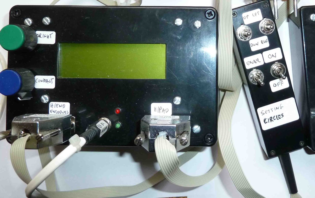
The circuit itself comprises the CPU, LCD display module and circuitry, keyboard debounce, and 5V regulated supply. The LCD module (Winstar WH2004A-YYH-JT#) takes up a large number of the CPU i/o pins. It can be driven through a 4-bit or 8-bit bus mode, and follows the industry standard for this kind of display – which is just as well as the Winstar documentation for the module is pretty much incomprehensible. The software uses the 4-bit mode.
The most complicated feature is the brightness control for the LCD backlight :) The LCD backlight is an array of LEDs mounted in the module, and takes between 200 to 400mA. The current has to be limited by some means, and
varied to control the brightness.
The most complicated feature is the brightness control for the LCD backlight :) The LCD backlight is an array of LEDs mounted in the module, and takes between 200 to 400mA. The current has to be limited by some means, and
varied to control the brightness.
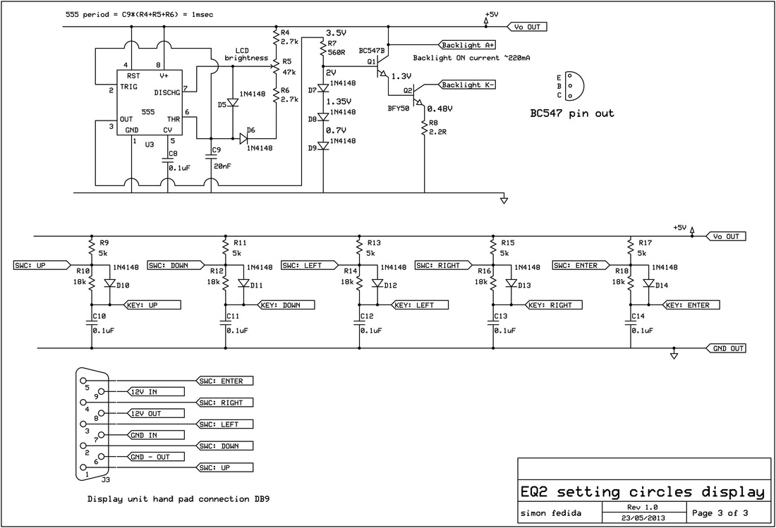
A constant current source transistor Q2 provides this. The current is determined by the emitter voltage of Q2 and load resistor R8. The emitter voltage of Q2 is determined by the base voltage of Q2 and that in turn by the base voltage of Q1. The base voltage of Q1 is set by the diode chain D7, D8 and D9, to be 2V. The constant current feature and temperature stability derives from the fundamental nature of the voltage drop across the forward biased PN junctions in the diodes and the transistor base-emitter junctions, which is a constant for our purposes. Q2 (BFY50) is a medium power transistor. Its large current gain, Hfe can be on the low side at 200mA collector current, so Q1 (BC547/ BC337 – low power, high gain) is added to supply the base current to Q2. The base current at Q1 is then fractions of a milliamp. The drive voltage for Q1 is the output of a 555 timer configured as a variable mark to space ratio oscillator running at about 1Khz. The backlight is off when the 555 is LO, and on when HI. The mark/space ratio can be varied over a 25:1 ratio by potentiometer R5, and this determines the backlight brightness.
The links below have the circuit diagram for the display unit electronics as a pdf, and also the C source code as pdf and a txt file. Rename the .txt file to a .ino file and it should be recognised by the Arduino system.
The links below have the circuit diagram for the display unit electronics as a pdf, and also the C source code as pdf and a txt file. Rename the .txt file to a .ino file and it should be recognised by the Arduino system.
| display_unit_all.pdf |
| s_circles_display_unit_c_code.pdf |
| lcd_3.txt |
Construction:
The Winstar LCD module is quite large, so a large enclosure is needed for the main unit. The extra space can be put to good use in the layout of the stripboard. In particular, extra plugs and sockets can be laid out so that the unit’s CPU can be pulled and an Arduino R3 board connected up to run the system. This is very helpful in developing and testing the system. The circuit includes a jumper plug to switch between Arduino board derived 12V and 5V supplies, and the front panel socket 12V and regulated 5V internal supply. The pictures here show the construction of the display unit.
The Winstar LCD module is quite large, so a large enclosure is needed for the main unit. The extra space can be put to good use in the layout of the stripboard. In particular, extra plugs and sockets can be laid out so that the unit’s CPU can be pulled and an Arduino R3 board connected up to run the system. This is very helpful in developing and testing the system. The circuit includes a jumper plug to switch between Arduino board derived 12V and 5V supplies, and the front panel socket 12V and regulated 5V internal supply. The pictures here show the construction of the display unit.
The main parts list is as follows – I have not listed the minor resistors and capacitors, or general ironmongery (threaded spacers, DB9 plugs, sockets etc).
Rapid Electronics (www.rapidonline.com)
1. 1x ATMega328 CPU with Arduino Uno Bootloader programmed, 73-4477
2. 1x 16Mhz 20ppm HC-49US Low Profile Crystal, 90-1428
3. 1x 57-2253 20x4 LCD Display Yellow/green LED Backlight
4. 3x Plug strip - 22-1705 TruConnect Turned Pin SIL Header 32-Way
5. 3x Socket strip - 22-1751 32 Way Turned Pin Sil Socket
6. If required - 1x Arduino Uno A000066 Board R3, 73-4440
7. If required - 1x Cable USB2 2m A Male to B Male, 19-8660
8. 1x L7805CV +5V 1A VOLTAGE REGULATOR (ST) , 47-3290
9. 2x 47-3136 1N4004 1A 400V SILICON RECTIFIER DIODE
10. 10x 47-3416 1n4148 Signal Diode 75v 150ma
11. 1x 82-0336 ST NE555 Bipolar Single Timer
12. 1x BFY50 transistor
13. 1x BC547/BC337 transistor 81-0399 Bc337-40 To-92 (c) 50v Npn
14. 1x 56-0400 Kingbright L-7104LID 3mm Red LED Low Current
15. 1x 56-0405 Kingbright L-7104LGD 3mm Green LED Low Current
16. 2x 55-0160 Kingbright 3mm LED Panel Clip
17. If required - 22-0114 Tube of 17 28pin DIL Socket, Narrow7.62mm with Central Support
18. 1x Potentiometer 10K
19. 1x Potentiometer 47K
20. 3x 75-0086 Spdt (on)-off-(on) Min Toggle Switch
21. 1x 75-0082 Spst On-off Min Toggle Switch
Sciencestore (www.sciencestore.co.uk)
1. Tripad Board, SRBP board 100 x 160mm with rectangular pads covering three holes at a time. Hole spacing 2.54 x 2.54 (o.1"), 39 strips x 20 (3 hole pads) Part No.: CDT0139
Maplin (www.maplin.co.uk)
1. Tripad board, Product Code JP52G (if you can’t get it at Sciencestore)
2. Enclosure box YN40T MB5 (display box)
3. Enclosure box FT31J Small Box (hand pad)
The circuit is constructed on tripad stripboard. Be aware that you will probably be inserting and removing the CPUs from the 28pin socket on numerous occasions. A flat bladed screwdriver is fine for this, but it helps to have access to both ends of the chip, so try and keep these areas clear of components so you can get the screwdriver into position. Wear an antistatic strap when handling the CPU. The little plugs and sockets to link the front panel LCD, DB9 connectors, LEDs are made from the plug and socket strip and a hot glue gun. Glue a piece of transparent plastic (from a CD case) over the window cutout for the LCD to protect the LCD screen. The remote keyboard handpad takes the 5 switches and the power on/off switch. Attach it with about 1m of cable. The 7805 regulator will need a clip-on
heatsink.
Software:
The software comprises several parts:
• LCD utilities – set of routines to control the LCD. Various primitive functions and a high level LCD print string function
• Read and debounce switches
• Read serial inputs and convert encoder position counts. CPU pin 14 is toggled every half bit time when reading the serial links and so can be monitored with an oscilloscope
• Star library – set of 24 bright reference stars to align the setting circles
• Screen menu display routines and option processing
The software version here is very much a first cut: enough to make a working system and to see how it runs. Some screen menu options are incomplete, and others are complete but probably not that useful. So a bit of re-work and improvements are in the pipeline at some point after more field testing.
The basic program flow is to optionally enter some key parameters and then perform a 1-star alignment, as
follows:
1. ‘hello world’ splash screen on power up for two seconds
2. Display calibrate backlash menu:
a. UP key to calibrate backlash parameters in units of encoder ticks. User is asked to complete 4 measurements:
i. Move RA to target in a POS-itive direction and key ENTER - User then moves in RA substantially more positive before returning
ii. Move RA to target in a NEG-ative direction and key ENTER
iii. Screen reports POS-itive RA backlash. Option to repeat or continue
iv. Move RA to target in a NEG-ative direction and key ENTER - User then moves in RA substantially more negative before returning
v. Move RA to target in a POS-itive direction and key ENTER
vi. Screen reports NEG-ative RA backlash. Option to repeat or continue
vii. Move DEC to target in a POS-itive direction and key ENTER - User then moves in DEC substantially more positive before returning
viii. Move DEC to target in a NEG-ative direction and key ENTER
ix. Screen reports POS-itive DEC backlash. Option to repeat or continue
x. Move DEC to target in a NEG-ative direction and key ENTER - User then moves in DEC substantially more negative before returning
xi. Move DEC to target in a POS-itive direction and key ENTER
xii. Screen reports NEG-ative DEC backlash. Option to repeat or continue
b. DOWN key to zero backlash parameters. RA and DEC forward and reverse parameters set to zero; user prompted to return to calibrate menu or move to next stage.
c. LEFT key to display current values of backlash parameters. User prompted to return to calibrate menu or move to next stage.
d. RIGHT key to set default backlash parameters. RA and DEC forward and reverse parameters set to default values of 75 ticks :); user prompted to return to calibrate menu or move to next stage.
e. ENTER key to automatically set default backlash parameters and move directly to next stage.
3. Display set encoder resolution menu:
a. UP key – enter RA resolution (ticks per revolution) (code not written yet)
b. DOWN key – set default value of RA resolution of 17817. User prompted to return to resolution menu or move to next stage.
c. LEFT key - enter DEC resolution (ticks per revolution) (code not written yet)
d. RIGHT key – set default value of DEC resolution of 17817. User prompted to return to resolution menu or move to next stage.
e. ENTER key to automatically set default backlash parameters and move directly to next stage.
4. Display shows current *unaligned* RA and DEC readings in both decimal degrees and RA (hrs,mn,s) and DEC (dg,mn,s). Display also shows which direction (POS or NEG) that each axis is moving in. Use any key to go to
next stage.
5. Select alignment star: Display shows first star in the alignment catalogue. User may scroll up and down the catalogue list with the LEFT and RIGHT keys, which is ordered alphabetically. When the desired star is
reached, then
a. ENTER key to continue alignment:
i. Display shows the star RA and DEC co-ordinates to which the mount setting circles will be set. ENTER to complete this alignment or UP to return to star list. The idea is that the user centres the target star centrally in the field of view of
the eyepiece, and the ENTER key confirms that fact to the software.
b. UP to leave alignment and go the next stage.
6. Screen displays RAM Free message: any key to continue.
a. Screen displays calibrate backlash menu: ENTER to skip
b. Screen displays set encoder resolution menu: ENTER to skip
7. Display shows current *aligned* RA and DEC readings in both decimal degrees and RA (hrs,mn,s) and DEC (dg,mn,s). Display also shows which direction (POS or NEG) that each axis is moving in. This is the default display for normal useage - use any key to return to (5).
Other setup issues:
When configuring the system for the first time the encoder direction sense needs to be checked. At stage 4 – display unaligned RA and DEC readings – check that:
1. The RA co-ordinate should increase as the RA shaft is rotated clockwise as viewed from the base of the RA casting
looking into the mount. If it does not, swap over the RA upper and lower sensor plugs in the head-end electronics box.
2. The DEC co-ordinate should increase as the DEC shaft is rotated clockwise as viewed looking along the counterweight shaft into the mount. If it does not, swap over the DEC upper and lower sensor plugs in the head-end
electronics box.
Clearly, adjustments such as this are better done in software rather than opening up the cases.
Improvements:
Storing parameters such as backlash values, any count-direction switches such as the above, axis resolutions etc, in the 1Kb of EEPROM of the ATM328 would be a good idea.
The next step in developing the software is any bug fixes after field testing, and then adding enhanced alignment algorithms using two and three stars in order to compensate for inaccurate polar alignment. A complete mathematical treatment of these algorithms can be found on Toshimi Taki’s very interesting web site at www.geocities.jp/toshimi_taki/
