EQ2 drive corrector (last updated 27 July 2013)
This project is an add-on to the standard EQ2 motor drive to improve its performance with an autoguider. Follow the link below for the circuit diagrams for the project as a pdf. Schematics are drawn with ExpressSCH from www.expresspcb.com– its free, simple, effective and the learning curve is only 5 minutes long.
| eq2_drive_corrector_schematic_all_pages_update_130711.pdf |
The EQ2 RA motor control paddle has 4 buttons on it, providing x4 speed, x2 speed, pause and 4x reverse speed. With no buttons pressed the motor runs at its default, normal sidereal speed. I have also grafted one of these RA motors and control paddles onto the DEC axis fine adjust spindle so two-axis autoguiding is possible.
Thinking about control of the RA motion for the moment: the autoguider will switch between ‘fast’ and ‘slow’ as the target object drifts to and fro in the guider sensor. When the guider wants ‘fast’, the motor drive needs to go at normal plus a bit. Switching the motor drive to 4x or 2x for the ‘fast’ mode is too brutal and the guider overshoots. In a similar way, switching the drive to pause when the guider wants slow (normal less a bit) causes the guider to undershoot. The solution is to synthesise ‘a bit faster’ as a continuous switching between normal and, say, 4x. And to synthesise ‘a bit slower’ as a continuous switching between normal and pause.
The circuit
The motor can be controlled remotely by wiring up relays to the contacts of the mechanical switches of the motor control paddle. Rather than relays this circuit uses the CD4066 logic chip. The CD4066 is a 14pin logic chip that provides four solid state switches. Each switch is a three wire device – a control pin, and the two contacts to be switched (which can be considered interchangeable for our purposes). The switch conducts when the control pin is HI. The ON resistance is around 200 ohms with a 5V supply.
A 555 timer configured as a free running variable mark-to-space oscillator is used to gate the motor between normal speed (the space) and the fast/slow speed (the mark). The circuit for control of the RA axis is shown in page 2 of the schematic. The period of the 555 timer is given by P=(R9 + R10 + R11*C4. This gives a value of 52 msec with the values shown. The minimum mark is 2.7msec and the maximum mark 50msec. The range of the control potentiometer is thus from almost no deviation from normal speed, to almost entirely the fast/slow speed selected.
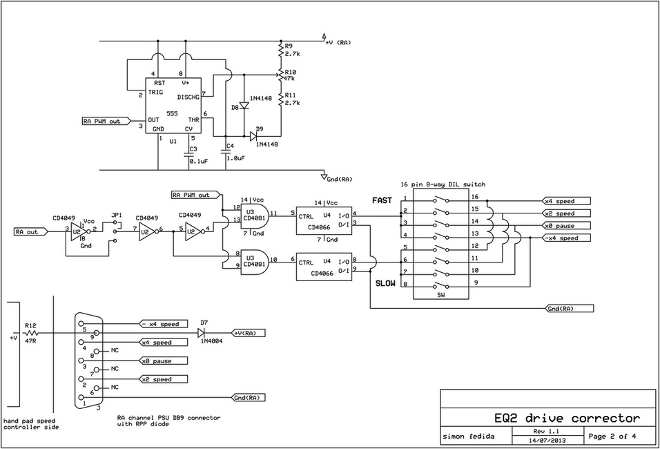
Reading the circuit from the left, input from the guider is expected as a varying logic hi/lo to represent ‘faster’ and ‘slower’. An inverter can be switched in via jumper JP1 to invert the sense if necessary. The signal is buffered and inverted to generate two, active-HI fast and slow signals into AND gates U3. These two fast and slow signals are by definition 180 degrees out of phase – ie not both HI at the same time. The gates U3 AND the fast and slow signals with the PWM output of the 555 timer, and the output is fed to the control pin of the CD4066 switches. Suppose the fast signal is HI, then the output of the AND gate fed into the CD4066 CTRL pin is a hi/lo train of pulses with a mark/space ratio that of the 555 timer. When the fast signal goes LO, the output of the AND gate is LO. Similarly for the slow signal.
Each of the two CD4066 switches are wired on one side to the wiper of 4 bits of two halves of an 8-way DIL switch, and on the other side to ground. The other side of the DIL switch is wired to each of the speed buttons of the motor control paddle. When the CD4066 conducts (control is HI), then ground is connected to whichever of the speed buttons is selected by the DIL switch, setting the motor to run at that speed, as though the mechanical button had been pressed. When the CD4066 is off, then no button is selected and the motor defaults to normal speed. (By the same token, if no speed buttons are selected by the DIL switch, the motor defaults to normal speed.)
In operation the fast side of the DIL switch is set to x2 or x4, and the slow side of the DIL switch to pause or left unset (if normal speed is slightly slow). The mark/space ratio of the 555 timer is adjusted so the guider gently hunts to and fro on the target.
Also shown on the circuit diagram is the wiring to the motor hand paddle. I chose to power the drive corrector from the motor battery pack, at a nominal 6V, and brought out the power line with the button contacts and ground as a ribbon cable using a 9way DSUB connector. As a precaution put a current limiting resistor R12 into the 6V pick up point in the motor control paddle, and an RPP diode D7 in series with the 6V line in case of accidents and polarities get reversed in the field.
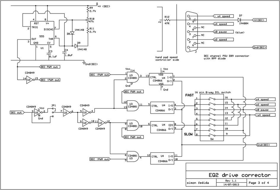
For the DEC axis guiding a second, separate circuit is needed powered from the second battery pack and connected to the second motor control paddle. Setting up the DEC axis is different from the RA. Normally the DEC motor is paused, with only small movements to catch up with any drift. While the RA drive is mostly normal speed, with a little bit of faster and a little bit of
slower, the DEC drive is mostly off, with a little bit of slow drive in one direction. For any half way adequate polar alignment, the DEC correction needed is usually very small – the available motor speeds will be far too fierce if left unmodified.
A very similar circuit to the RA side is used, the difference is that while the default RA condition is normal speed, the default DEC condition is paused. For the RA side, no paddle switch selection is needed to select normal speed, but for the DEC side the pause button must be connected to ground to obtain off. So, for each of the fast and slow side of the DEC channel, an additional CD4066
switch is needed to make this connection in the PWM off phase. The potentiometer should be wired so that the minimum position produces a ‘mostly paused’ motor condition.
In operation the fast side of the DEC DIL switch is set to normal speed (no DIL switch setting), and the slow side of the DIL switch to pause. The mark/space ratio of the 555 timer is adjusted so the guider gently hunts to and fro on the target. Depending on exactly how the autoguider functions, the slow side of the DIL switch could be set to -4x speed – so that as the telescope guides past the meridian and the DEC drift reverses, the correction also reverses.
Connecting to the autoguider
The interconnect to the guider is shown in page 1 of the schematic. The guider RA control signal is a 50 ohm impedance hi/lo 5V logic level. The DEC control signal is a simple on-off relay. The interface is clearly not an Ascom compliant device, but hopefully there is enough info here to adapt it if needed.
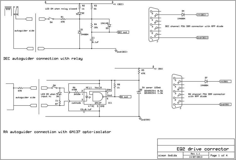
The DEC signal interface is a simple debounce circuit for the relay with an LED on/off indicator. R1 and D1 are protection components in case a power plug is inserted by mistake.
The RA interface uses the input logic level signal to drive an optocoupler, 6N137 and an LED on/off indicator. The 6N137 is a strictly 5V supply device, so a simple zener diode D5 is used to clip its Vcc from the battery rail at 5V.
Construction – Circuit board
Here are some pics of the project, pretty much self-explanatory. Most of the parts are from Rapid Electronics (www.rapidonline.com – components, plugs and sockets, wire and ironmongery) and Maplin (www.maplin.co.uk – tripad board, case, shrink wrap tube etc).
The circuit was assembled on tripad prototyping board (Maplin, product code JP52G). The little plugs and sockets to connect the front panel to the board are made from plug and socket strip (Rapid, 32 Way Turned Pin Sil Socket Part #22-1751 and Turned Pin SIL Header 32-Way Part #22-1705). For example, to make a ribbon cable from panel plug to circuit board, use a knife to cut the right length of header and socket from the strips, snip off the pins on the header (NOT the pins that fit in the socket – they are of a different size), and solder the wires to the stubs that are left. Encapsulate this termination with glue from a hot glue gun and you have a great plug and socket system.
Construction - Motor control paddle modification
Here are some pics of how to modify the control paddles. First off use a small flat bladed screwdriver to (gently) lever off the button tops of the speed switches. Remove the four screws on the front panel and from the DC socket on the bottom. Lift off the front panel and feed through the motor cable to give some room to work. At this point it is probably a good idea to drill a hole in the case to take the new cable. A 9way ribbon cable rolls up nicely to fit a 4mm diameter hole in the case. Thread a 1m length of cable through the hole. Undo the two screws holding the daughter board with the buttons to the main board. Unscrew the main board from the base of the case.
Identify the 6 Volt pick off pad on the main board. Electrically it is after the on-off switch. Drill a small hole in the board next to the pad and feed through the wire of the current limiting safety resistor. Solder it to the pad. Use a hot glue gun to secure the resistor body to the top side of the main board. On the daughter board solder wires to the switch contacts on the back, including the common/ground (this is the wire with the red reference stripe in the pics. If this wire is numbered 1, wire 2 connects to x2 switch, wire 3 to pause, wire 4 to x4 speed, wire 5 to -4x speed. Wires 6,7,8 are not connected). Then connect wire 9 to the resistor on the main board and insulate it with a bit of shrink wrap tube.
Arrange the cable under the daughter board and screw the daughter board back onto the main board. Feed the motor cable and the new switch cable back through their respective holes until the main board fits snugly in position. A cable tie pulled tight on the new switch cable each side of the case wall will trap the cable and prevent it pulling. Screw the main board down and reassemble the case. Push the button tops back on. Wire up a DB9 socket and shells on the other end of the cable to match the connection to the corrector circuit. Check and double check all the connections thoroughly with a multimeter, make sure switches connect to ground when pressed etc, and that should be it.
Arrange the cable under the daughter board and screw the daughter board back onto the main board. Feed the motor cable and the new switch cable back through their respective holes until the main board fits snugly in position. A cable tie pulled tight on the new switch cable each side of the case wall will trap the cable and prevent it pulling. Screw the main board down and reassemble the case. Push the button tops back on. Wire up a DB9 socket and shells on the other end of the cable to match the connection to the corrector circuit. Check and double check all the connections thoroughly with a multimeter, make sure switches connect to ground when pressed etc, and that should be it.
